- Start iWay Service Manager. From the Windows Start menu, select Programs, iWay 6.0 Service Manager, base.
-
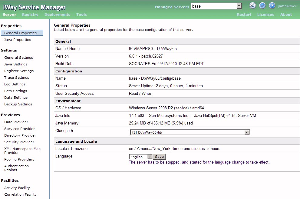
Open the iWay Service Manager Console. From the Windows
Start menu, select Programs, iWay 6.0 Service Manager, console.
The iWay Service Manager opens, as shown in the following image.
Note: The directory that contains the database jar files must be included in the system classpath. Typically, this directory is install_drive:\Program Files\iway60\lib.
- In the top-left window, click Registry to enter the environment where you design iWay components.
-
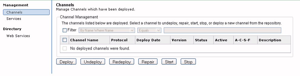
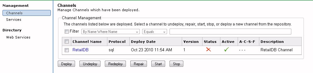
In the left pane, under Components, select Listeners.
The Listeners dialog box opens on the right, as shown in the following image. From this dialog box you can see a list of previously configured listeners and create new listeners.
-
To create a new listener, click Add.
The Select Listener Type dialog box opens.
-
From the Type of the new listener drop-down list, select
the appropriate type of listener for the data source you want to
monitor.
In this example, the data source is a database, so the listener type is RDBMS, as shown in the following image.
Tip: You can also use a Relational Database High Water Mark (RDBHWM) listener, which is useful when you have read-only permissions and you want to select records that exceed a high water mark, such as a last-update time of day value. For details on the RDBHWM listener, see the iWay Service Manager Extensions User's Guide.
-
Click Next.
The Configuration parameters dialog box opens. The following image shows part of the parameters dialog box for the RDBMS listener. Use the scroll bar to access all properties in the window.
-
Type and select the configuration properties appropriate
for the listener. See the iWay Service Manager User's Guide for
details on listener properties.
The following are some recommended settings for Magnify:
- Set Accepts non-XML (flat only) to false.
- Set Optimize Favoring to performance.
- Set Default Java Encoding to UTF-8.
- Set Record Activity Log(s) to false.
The Multi-threading and Polling Interval settings can be used to optimize the Magnify platform.
Note: SQL Query is how to get new data in the table. SQL Postquery is responsible for updating the table after a record has been read by the listener. Controlling the post query operation as part of the process flow may be optimal. For example, for larger bulk processing where queries need to be limited by rows returned.
- Click Next.
-
Type a name and description for the listener.
To continue with the example established in the Magnify Search Feed Example, we will name the listener, Retail_DB.
-
Click Finish.
The Listeners pane is refreshed with the new listener, as shown in the following image.
Now we will create the inlet that will hold the listener.