Creating the Indexing Process Flow
This section explains how to create and configure the
indexing process flow, which will be incorporated in the iWay channel.
xAbout the Transaction Indexing Process Flow
This section explains how to use the iWay Designer
tool to create, validate, and test the transaction indexing process
flow. For additional information on iWay Designer, see the iWay
Designer User's Guide.
The following image shows an indexing process flow created
with iWay Designer. For illustrative purposes, the names of the
objects in this process flow match their function, but you can use
other descriptive names, as needed.
As you add objects, such as Store Values and Create HTML, to
the process flow, you must build a relationship between them.
The relationship between objects is represented by colored lines
connecting the objects. These lines also show the movement of
a document through the process flow.
The following procedure explains how to create the indexing
process flow.
x
Procedure: How to Create a New Process Flow
-
Start iWay Service Manager. From the
Windows Start menu, select Programs, then iWay
6.0 Service Manager, then base,
then Start Service Manager - base.
-
Start iWay Designer. From the Windows Start menu, select Programs,
then iWay 6.0 Service Manager, then tools,
then iWay Designer.
iWay Designer opens, as shown in the following image.
-
Create a project for the process flow in the Registry
Based repository, as follows:
Note: A Designer project can contain more than
one process flow, so this step is not necessary if you want to
create the process flow under an existing project. In this case,
go to Step 4.
-
In the navigation pane, right-click the
repository you want to work in (in our example, iWay) and select
New Project.
-
In the Designer Project Information dialog box, name
the project, provide a brief description, and click Next.
-
In the Designer Project Bindings dialog box, select
iWay Registry.
-
Click Finish.
The new project appears under the repository.
Our
example project is named Sporting Goods.
-
In the Navigation pane, expand the Project node.
-
Right-click the Processes node and select New
Process.
-
In the iWay Process Configuration dialog box, name
the process flow and type a brief description.
-
Click Finish.
The new process flow node appears under Processes in the
Navigation pane and a Start object appears in the workspace, as
shown in the following image.
Our example process flow is
named Goods_Index1.
The
Start object begins the process flow by accepting the XML document containing
data from your data source by way of the iWay listener.
To
view the Start object properties, right-click the object in the
workspace and select Properties. While in
this dialog box, you can rename the object (Name tab).
Continue
creating the process flow using the instructions found in Storing Metadata Values.
x
Next, you must configure a Service object to define
the metadata that will identify the fields in the incoming XML document
that you want to appear in the Categorization Tree, as well as
the field or fields that will uniquely identify the record when it
is indexed.
The metadata parameters you will use are FXVn and
FXKn. Keeping with the example in Overview of Implementing Magnify, we will define metadata parameters for Brand, Category, Color,
Department, Gender, Price Range, Promotion, Sports, and Style.
And the identifier will be product ID.
You can use multiple identifiers for a record, if necessary.
For example, if you were indexing employee information, you could
use the last name of the employee as the unique identifier, or you
could use the last name and the first name to ensure there would
be no duplicate records. To define multiple identifiers, use the
parameters FXK, FXK2, FXK3, FXK4, and so on. (The FXK parameter
implies FXK1.)
You can also specify multiple values for a field by using the
FXMn parameter. FXMn is used in place of FXVn when
using multiple values and contains a unique delimiter that is used
to assign each value its own category in the dynamic categorization
tree. The delimiter can be any value, but it should be unique and
not used in the field value. You must use delimiter as the
metadata parameter name to define the delimiter value. The delimiter
value is defined once and applied to all FXMn meta tags in
the Service Object. Therefore, the delimiter must be the same for
all FXMn values.
Note: The FXMn metadata parameter is not available
in the Magnify Prototype Wizard.
x
Procedure: How to Store Metadata Values
-
Select the Service object icon from
the toolbar and drag it to the workspace.
-
In the New Service Object dialog box, name the object
and type a brief description.
Using our example, the object name is Store Values.
-
Click Next.
The Service Type dialog box opens.
-
Select Class Name and in the Class
Name field, type XDSREGAgent.
Important: This is not an arbitrary name. XDSREGAgent
is the exact name of the class.
The following image shows
the Service Type dialog box with the class name field populated.
-
Click Next.
-
In the Define Service dialog box, select Define
Service Globally, as shown in the following image. (This
makes this object available for use in other processes.)
-
Click Next.
The Properties dialog box opens.
-
Leave this dialog box as is, and click Next.
The User Defined Properties dialog box opens, as shown
in the following image.
In
this dialog box we can identify and the specific which metadata
from the incoming XML document you want to appear in the Dynamic
Categorization search results tree using the following metadata
parameters:
- FXVn. Parameter for the desired
field value (where n is the sequential number of the field
value you are identifying. Start with FXV1 and continue to FXV2,
FXV3, and so on.
- FXM. Parameter for a desired field that contains multiple values.
FXM is used in place of FXVn and contains a unique delimiter
that is used to assign each value its own category in the dynamic
categorization tree. The delimiter can be any value, but it should
be unique and not used in the field value. You must use delimiter
as the metadata parameter name to define the delimiter value. The delimiter
value is defined once and applied to all FXMn metatags in
the Service Object. Therefore, the delimiter must be the same for
all FXMn values.
For example, the following image shows
several FXM values and a ZXZ delimiter value specified by
the delimiter user-defined property name:
Note: The FXM
metadata parameter is not available in the Magnify Prototype Wizard.
- FXK. A unique identifier for the incoming record. Use the following
parameters for multiple identifiers; FXK, FXK n,
where n = 2, 3, 4, and so on (FXK implies
FXK1).
For more information on metadata parameters,
see About the Magnify Feed Process.
-
Double-click in the Name field and type FXV1 to represent
the first field value you will define. The Type is string.
-
From the Value drop-down list, select Create
XPath expression.
Note: An XML Path Language (XPath) expression defines
the path to a specific value (or values) within an XML document.
This path is based on the hierarchal structure of the XML document.
This step ties the property name (FXVn) to
the location in the XML file that holds the property value (the
XPath expression).
The XPath Builder wizard opens.
-
In the XPath Builder dialog box, click Load
XML File to load a document instance, and browse to
an XML document that will be coming into the process flow.
The XML document appears in the document pane. The following
image shows an XML document in the Load a document instance dialog
box.
-
Click Next.
The Build an XPath dialog box opens.
-
In the left pane, expand the XML document node to expose
the elements, then double-click the element you want in the XPath
expression.
In our example, we want to include the value of Brand,
therefore, expand the RetailDB node, and select the Brand field, retaildb.Brand.
The
following image shows an XML structure in the left pane with the
Brand element selected for the XPath expression.
Using
our example, the path to the Brand element appears in the XPath
field, and the Brand element value and occurrence in the XML document
appears in the right pane.
-
Click Next. In the next dialog
box, click Next, and in the last dialog box,
click Finish.
The XPath expression appears in the Value field, as shown
in the following image.
With
the FXV1 parameter, we have identified an item we want to appear
in the Dynamic Categorization tree by locating the XML field where
it resides.
-
Continue to add the items for the Dynamic Categorization
tree using Steps 9 through 15.
The subsequent parameter names for our example field values
are:
FXV2 with a value of an XPath expression pointing to
the retaildb.Category field.
FXV3
with a value of an XPath expression pointing to the retaildb.Color field.
And
so on, through to FXV10 pointing to the retaildb.Style field.
-
Once all the metadata you require is defined, add one
or more unique identifiers for this data (FXK and FXKn for
multiple identifiers) using the same method as for field values.
In our example, the productid is
the unique identifier of this record.
Note: The order
in which you enter the values and the key identifier is not critical.
However, the FX meta tags must be in sequential order. If a set
of FX meta tags are removed, the remaining meta tags must be renumbered.
Otherwise, the links on the Dynamic Categorization tree will produce
an error.
The following images shows the User Defined Properties
dialog box with our example of ten defined parameters and their
unique identifier.
-
Click Finish. The Service object
appears in the workspace.
-
Build a relationship between the Start object and the
Store Values object with the Event option set to OnCompletion.
The following image shows the process flow with the Store
Values object.

Continue
creating the process flow using the instructions found in Creating the HTML Document.
xCreating the HTML Document
Once you have identified the incoming data field values
you want, you must convert the XML document to an HTML document
using a Transform object. In this HTML document, you define the
links associated with the field values that were set up in the
Store Values object.
A Transform object within the process flow triggers an XML-to-HTML
transform that has been designed with the iWay Adapter Transformer
tool. As you configure the Transform object, you can design a
transform that maps the XML elements to HTML elements. As a minimum
you must map the fields that were designated for the Dynamic Categorization tree,
and then map any additional metadata, content, and paths to images
and WebFOCUS reports to be invoked from the search results interface.
The Dynamic Categorization tree fields we will map from our
example are Brand, Category, Color, Department, Gender, PriceRange,
Promotion, Price, and Style. We will also add the information to
call the WebFOCUS report, include the two additional links, and
add a few images, as noted in About the Magnify Feed Process.
The following procedure provides the details to create the
XML-to-HTML mapping while maintaining the required HTML format.
You can refer to your Configuration Worksheet for the information
needed to set up the mapping.
x
Procedure: How to Create an HTML Document
To
create an HTML document from the incoming XML document:
-
Select the Transform object icon from the toolbar
and drag it to the workspace.
-
In the New Transform Object dialog box, name the object
and type a brief description.
In our example, the object name is Create HTML.
-
Click Next.
The Transform Type dialog box opens, as shown in the following
image. By default, New Transformer appears in the Transform field.
Note: Once
a transformation is created and published, it becomes available
in the Transform drop-down list. This procedure explains how to
create a new transform.
-
Click the Launch Transformer button.
The iWay Adapter Transformer tool, shown in the following
image, opens in a separate window.
-
To start the Project Wizard, from the main menu select
File, then Project Wizard.
The Project Location dialog box opens, as shown in the
following image.
-
Type a name for the transformation project and browse
to the location where you want to store it.
The transform for our example is named XMLtoHTML_Search.
-
Click Next.
The Project Type dialog box opens, as shown in the following
image.
-
Select XML in both the From pane and the To pane.
Note: Because XML provides a certain flexibility
and can be used to produce an HTML document, you can choose XML
as the output format for the XML-to-HTML transform.
-
Click Next.
The Input Properties dialog box opens, as shown in the
following image.
-
In the Structure tab, browse to a file that represents
the XML document that will come from the listener.
Note: All iWay listeners produce an XML formatted
file.
-
In the Data tab, browse to a sample XML data input
file that can be used to test the transformation.
-
In the Validation tab, select an option for validating
the XML input document during run time.
The following image shows the Validation options.
-
Click Next.
The Output Properties dialog box, shown in the following
image, opens.
Note: If
you have a template of the output structure, browse to it in the Structure
field. This is helpful, but not necessary, when building the output
structure in the mapping step of this procedure.
For the
required HTML output structure, see Creating the HTML Document.
-
Click Finish.
The project appears in the main Transformer window, as
shown in the following image. The Input Items Structure pane reflects
the XML input file structure and the Output (unless you provided
a template) contains the Target_Root tag. You will build the HTML
output structure under this root tag.
As
noted in Creating the HTML Document, the HTML document you send to the search
engine must have a specific format. The following tables list the required
HTML parameters and values when using:
- A standalone report
procedure.
- A Managed Reporting report procedure.
- An external URL.
Use the information you recorded
in the configuration worksheets as you build the HTML output. For
more information, see Magnify Meta Tags.
In the subsequent steps of this procedure,
we will build our HTML output using the standalone report procedure
parameters.
-
Rename the Target_Root tag, and create the HEAD and
TITLE tags, as follows:
-
In the Output Items Structure pane, rename
the Target_Root tag to HTML. (Right-click
the tag and select Rename.)
-
Right-click the HTML tag and select Add,
Parent from the drop-down list.
-
An Output_Parent_Tag appears under the HTML tag. Rename this
tag HEAD.
-
Right-click the HEAD tag and select Add,
Element. An Output_Element_Tag appears under
the HEAD tag. Rename this tag TITLE.
Give the TITLE tag a value, as noted in the previous
table, that corresponds to the title you want to appear as the
search result link.
When you assign a value to an output
item, you can:
- Select from Input (select an item from
the input structure)
- Use Functions. Select a function that operates on the input
value. Use this option to concatenate strings.
- Type a Constant (type a constant value).
- Use an Expression.
-
Highlight the TITLE tag, then in the Mapping pane,
click the ellipsis (...).
The Edit - Output Item Mapping dialog box opens, as shown
in the following image.
-
Select Type in Constant.
The Type in Constant field becomes available, as shown in the following
image.
-
In the Constant field, type the title for the search
result.
In our example, the title is Acme Delux ClassicBaseball
Spike Mens.
-
Click OK.
The TITLE tag mapping field (in the Output Items Mapping
pane) is populated. The following image shows these elements in
the Output Mapping pane.
-
Add the required META tags for the items in the Dynamic Categorization
tree. For each item, create a META tag that contains two attributes (name
and content), as follows:
-
Right-click the HEAD tag and select Add,
Element. An Output_Element_Tag appears under
the HEAD tag. Rename this tag META.
-
Right-click the META tag and select Add,
Attribute from the drop-down list.
An Output_Attribute appears under the META tag.
-
Rename the Output_Attribute tag name.
-
Add another attribute to this META tag and rename
it content.
-
Click the name attribute ellipsis, and in the Edit
dialog box, select Type in Constant.
-
In the Constant field, type the name for the Dynamic Categorization
tree.
Using our example, we type Department.
-
Click OK.
The name Mapping field is populated with your entry.
-
Click the content attribute ellipsis, and in the Edit
dialog box, choose Select from Input.
-
Expand the row node and select the value for META
tag.
Select the retaildb.Department field
to point to the value for Department in the database, as shown
in the following image.
-
Click OK.
The name Mapping field is populated with your entry.
The
following image shows the new mapping for the Department META
entry. (You can set the View to represent the mapping between
input and output items as a line.)
-
Using this same technique, enter the remaining Dynamic Categorization
items as META tags.
-
Continue by mapping the WebFOCUS report information
you want to associate with the link, as follows.
-
Create an element under the HEAD element
and rename it META.
-
Create two attributes for the new META element (Add,
Attribute), as described in Step 16.
-
Click the name attribute ellipsis, and in the Edit
dialog box, select Type in Constant.
-
In the Constant field, type the parameter for the
link title, as follows:
FOCEXEC_FOR_TITLE
-
Click OK.
The name Mapping field is populated with your entry.
-
Click the content attribute ellipsis, and in the Edit
dialog box, select Type In Constant.
-
Type the FOCEXEC that you want to use for this link.
The FOCEXEC in our example is prddet.
The content
Mapping field is populated with your entry, as shown in the following
image.
-
Continue using this method to add the remaining WebFOCUS report
parameters:
FOCSOURCEDATABASE_FOR_TITLE
FOCEXECAPPNAME_FOR_TITLE
-
Add META tags for the additional links.
The additional links in our example are Product Sheet
and Summary Report.
-
Add a META element under the HEAD element,
and add two attributes (name and content) as previously described.
-
Click the name attribute ellipsis, and in the Edit
dialog box, select Type in Constant.
-
In the Constant field, type the parameter name for
the link, as follows:
LINK_DISPLAY_NAME1
-
Click OK.
The name Mapping field is populated with your entry.
-
Click the content attribute ellipsis, and in the Edit
dialog box, select Type In Constant.
-
Type the name you want to appear in the search results
page as this link.
In our example, the link name is Product Sheet.
We also want a PDF icon to appear next to this name, so we include
the path to the image in this element content, as follows:
content = "Product Sheet <img src="http://vlamdemo.ibi.com:8080/
ibi_html/javaassist/images/mr/mr_ex_pdf.gif" border="0">"
-
Continue using this method to add the remaining META elements,
which identify the WebFOCUS report associated with this link, as follows:
-
FOCEXEC1
-
FOCSOURCEDATABASE1
-
FOCEXECAPPNAME1
The
following shows the META elements in the Output Items Mapping
pane.
-
Add another META element under the HEAD element, and
add two attributes (name and content) as previously described. This
element will define a second link, if desired. The entries are all
Type In Constant.
In our example, the second link is Summary Report.
Our entries for this example are:
META name = "LINK_DISPLAY_NAME2" content = "Summary Report"
META name = "FOCEXEC2" content = "prdsum"
META name = "FOCSOURCEDATABASE2" content ="retaildb"
META name = "FOCEXECAPPNAME2" content = "retail"
-
Add the BODY element. This element contains all possible
items and text that a user can search on to retrieve this record.
Note: Because this element can contain lengthy
content, you can use the concatenate function to join strings,
as shown in this procedure.
-
Under the HEAD element, add an element and rename
it BODY.
-
Click the BODY ellipsis in the Mapping pane.
-
In the Edit - Output Item Mapping dialog box, select
Use Functions. The function selections
appear in the Edit dialog box, as follows:
-
Select a concatenate function (@CONCAT) based on the
number of items in the XML document you want to include in the body.
The Parameter and Parameter Value fields appear below
the function pane.
Note: We recommend that you include
all of the items from the XML document in the body. You can also
add additional words or phrases you think will help locate this
record.
Tip: Use the following guidelines when
working with the concatenate functions.
- Each parameter
(Param1, Param2, Param3, and Param4) in the concatenate function
can then hold another concatenate function, and each of those,
another concatenate function, meaning you can nest concatenates
to produce a string to hold the content needed.
- In addition to XML items, the concatenate parameters must also
provide the spaces between these items in the BODY element. Therefore,
each concatenate that contains four parameters can hold two values
and two spaces.
- When nesting Concatenate functions, you must create the layers
of the nest and start defining the parameters in the innermost
concatenate function.
To illustrate nesting Concatenate
functions, use our example XML document, which contains 13 items
that we want to include in the BODY element. In addition, we want
to include the word Sporting to make a total of 14. Because we
have so many items to include, we select the @CONCAT(Param1, Param2,
Param3, Param4) function to start. The following diagram shows
the structure of the nested concatenate functions to join the
desired string values and spaces for the record in our example.
Note:
- Considerations should be made in preparing data earlier in the
process.
- If you can concatenate at the database level (for example, as
a virtual field or within a view), you will not have to manually
concatenate.
-
To define Param1, click the ellipsis to the right
of the Param1 Parameter Value field.
The Edit -- Param1 window opens with the same options
(Edit from Input, Use Functions, Type in Constant, and Use Expression).
-
Select either Select From Input to type
an actual value, or Use Functions and
select another concatenate function to continue nesting the concatenate
function.
The value of our example Param1 will be @CONCAT(Param1,
Param2, Param3, Param4). The following image shows the first concatenate
selection (Step d) in the left Edit window, and the Param1 Edit
window in the right Edit window.
Note: An
additional Edit window appears each time you select a function
as a parameter value.
-
In the Edit -- Param1 window, click the ellipsis for
Param1 Parameter Value and choose Select from Input.
-
In the Select from Input pane, expand the row element
and select the database field you want this parameter value to be.
From our example, we select Department for the
Param1 value.
-
Click OK.
The Parameter Value field is populated with this value.
-
To create a space between this value and the next,
click the ellipsis for Param2 Parameter Value and select Type
in Constant.
-
Press the space bar to input a space, then click OK.
-
Click the ellipsis for Param3 Parameter Value and
choose Select from Input.
-
In the Select from Input pane, expand the row element
and select the database field you want this parameter value to be.
Using our example, we choose Category for Param3.
-
Click OK.
The Parameter Value field is populated with this value.
-
To create a space between this value and the next,
click the ellipsis for Param4 Parameter Value and select Type
in Constant.
-
Press the space bar to input a space, then click OK.
The following image shows the original Edit window and
the Edit -- Param1 window. In the Edit -- Param1 window, we have
assigned values for the 4 parameters of the Parma1 concatenate.
Note that parameters 2 and 4 contain spaces.
-
In the Edit -- Param1 window, click OK.
The Edit -- Param1 window closes and the concatenate
value appears in the Parameter Value field of the original Edit
window, as shown in the following image.
-
Continue defining the remaining parameter values and
adding spaces using this method.
The XML to HTML transform project is now complete. The
following image is an example of the mapping between the input
and output structure that shows the META tags and the BODY tags
mapped to the original XML elements. (This image only shows one
expanded META element to reveal its mapping.)
-
Save the transform project (File,
Save Project).
-
To test the transformation, click the Test
Transform tab (located above the Input Items and Output
Items panes), or from the main menu, select Transform,
then Test.
The transformation output is then indexed and becomes part
of the content of a record.
The test results, which are the
resulting HTML documents, appear in the Test Transform pane.
For
more information on the structure of the document, see Magnify Protocols for Indexing Documents.
-
Publish the transformation so that it is available
for use by the iWay Adapter Manager, as follows:
-
From the File menu, select Publish Project.
-
In the Transform Properties dialog box, type a name
for the project and a brief description, and select an encoding
protocol from the Encoding drop-down list.
-
Click Next.
The Transform Location dialog box opens.
-
In the Repositories pane, expand the server node of
interest and select the configuration to which you want to publish
the project.
Note: The Transforms pane lists the transform
projects that exist in the selected folder.
-
Click Next.
-
In the Publish Transform dialog box, confirm the details
of the publication and make any necessary changes.
-
Click Publish.
-
In the confirmation window, click OK.
The transform now resides on the iWay server and configuration
you selected and is available for selection in the Adapter Designer
Transform object.
-
In the Adapter Designer Transform object, click Reload
Transforms to load the available transforms, which
includes the transform you just created.
-
From the Transform drop-down list, select the XML to
HTML transformation you just created for this search indexing.
For our example, select XMLtoHTML_Search.
-
Click Next.
-
Click Finish.
The Transform object appears in the Designer workspace.
-
Build a relationship between the Service object and
Transform object with the Event option set to OnCompletion.
The following image shows the process flow with the Create
HTML object.
xFeed HTML Document to the Search Engine
The Feed to Search Engine object is another Adapter
Designer Service object. Here you will include the database field
values we stored in the Store Values object (FXVn,
FXMn, and FXK) and add two parameters to
define the items in the search results Dynamic Categorization
tree:
- FXFn, which is the database field
for the entry in the search results Dynamic Categorization tree.
- FXTn, which is the descriptive title
that appears for the entry in the search results Dynamic Categorization
tree.
The FXK meta tag is not used in building the Dynamic Categorization
tree.
Security parameters are added to this Service object to enforce
access to search results. See the Magnify Security and
Administration Manual for information on the security feature.
For more information on feeding HTML documents to Magnify, see Magnify Protocols.
x
Procedure: How to Feed the HTML Document to the Search Engine
-
Select the Service object icon from
the toolbar and drag it to the workspace.
-
In the New Service Object dialog box, name the object
and type a brief description. In our example, the object name
is Feed to Search Engine.
-
Click Next.
-
In the Service Type dialog box, select iEI Feeder from
the Type drop-down list, as shown in the following image.
-
Click Next.
If the IEI_Feeder type is not an option in the Type drop-down
list, complete the following steps using the iWay Service Manager
Console:
- Click Registry.
- Click Components and then Services.
- Click Add.
- Select IEI Feed Agent {com.ibi.agents.IEIFeedAgent} from the
drop-down list.
- Specify the required values based on your environment.
- Specify a Name, such as IEIFeedAgent.
- Restart iWay.
The IEI Feed Agent is manually selected
during the iWay Service Manager installation. If the IEI Feed Agent
is not available, please contact your systems administrator.
-
In the Properties dialog box, shown in the following
image, type the appropriate values for the requested properties.
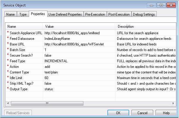
All items marked with
a red asterisk require a value.
The Properties are:
-
Search Appliance URL. URL
to the servlet that will feed data to the search engine. For example:
http//host:[port]/wf_context_root/saxfeed
where:
- saxfeed
Is the servlet.
Note:
- In Release 8.0 Version 01, any feeds designated for xmlfeed
or xmlfeedtest are redirected to saxfeed.
- Sample or default URLs are for informational
purposes only and may not resolve correctly, if at all.
-
Feed Datasource. Source of the data to be fed to the
search engine. To dynamically partition the index libraries, specify ?indexname as
the name of the datasource. You can also specify the size limit
in which the index should be partitioned as follows:
?
indexname
:
sizelimit
where:
-
indexname
-
Is the name of the index library.
-
sizelimit
-
When the index reaches the size limit, a new index library
is created. For example, a value of 100m creates a new index folder
when the current index reaches 100MBs. A new folder with the datasource
name and a sequential number is created. For example, retail,
retail1, retail2.
-
Base URL. URL to the WebFOCUS servlet (WFServlet),
which runs WebFOCUS reports. When a search result link is clicked,
the Base URL is prepended to the parameters associated with the
link, allowing the parameters to be passed to the WebFOCUS servlet
to run the report.
The Base URL format is
http//host:[port]/wf_context_root/WFServlet
where:
- host:[port]
Is the server and port number where WebFOCUS is installed.
- wf_context_root
Is the WebFOCUS web application context root. The default
is ibi_apps.
-
Batch Size. Number of records in a feed going to the
search engine.
When the Batch Size is greater than 1, the same
datasource must be used for all items in the batch.
-
Secure search? Specify true, to use HTTP basic authorization
to secure feed and queries.
-
Feed Type. FULL replaces all previous data in the index
from this data source, INCREMENTAL adds new data to existing index.
-
Action. Specify add to update
items in the index. Specify delete to remove
items from being searched. The value specified must be in lowercase.
-
Content Type. MIME type of the content to be indexed.
-
Idle Limit. Maximum time (in seconds) a feed can wait
before posting to the search engine.
If the Batch Size parameter
is set, it is recommended to use the Idle Limit setting as well.
If the Batch Size is not met after the Idle Limit time has expired,
the process flow sends Magnify the records that have been collected.
For example, if Batch Size is set to 4 and only three records are
sent to the process flow, the Batch Size setting has not been met.
However, after the Idle Limit time is met, the IEI Feed Agent sends
the three records to Magnify for indexing.
-
Strip XML Tags? Remove any XML characters from the feed.
-
Output Type. Output what is input, or output an XML status document.
Note: The
IEI Feed Agent is semi-synchronous. Once the document is sent to
Magnify, the connection no longer exists. If the agent does not
successfully send the document to Magnify, it stores the document
in the iWay60\config\base\etc\iei directory for later retrieval.
-
Click Next.
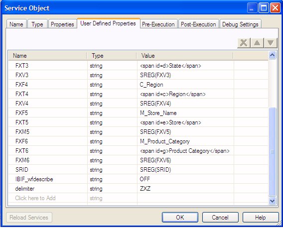
The User Defined Properties dialog box opens. As noted
in Feed HTML Document to the Search Engine, you will define the database field (FXFn),
the title for the result search category (FXTn),
as well as include the field values (FXVn and/or
FXMn) and unique identifier(s) (FXKn)
defined in the Store Values Service object (See Storing Metadata Values). In addition to these properties, you can define
the security parameters to enable the security feature.
For
more information on Magnify security, see the Magnify Security
and Administration Manual.
Note: The FX meta
tags must be sequential in order. If a set of FX meta tags are removed,
the remaining meta tags must be renumbered. Otherwise, the links on
the Dynamic Categorization tree will produce an error.
Type
the names and values manually using the following steps.
-
In the first Name field, type FXF1.
The Type is string.
-
In the Value field, type the value for the database
field.
From our example, we will type Department.
-
In the Name field, type FXT1, and in the Value field,
type a value for the title the search will return.
Using our example, the title for this field will be Department.
-
In the Name field type FXV1, and in the Value field,
type SREG(FXV1). This corresponds to the parameter you defined
earlier in the Store Values object.
Important: When adding the information for a field
that contains multiple values, you must specify FXM as the meta
tag name instead of FXV. You must also specify the delimiter that
is used for the multiple values. The delimiter value is defined
once and applied to all FXMn meta tags in the Service Object. Therefore,
the delimiter must be the same for all FXMn values.
For
example, the following image shows several FXM values and a ZXZ delimiter
value specified by the delimiter user-defined property name:
-
Continue by typing the values for the desired database
fields (FXF2, FXT2, FXV2, FXF3, FXT3, FXV3, and so on).
-
Type the name of the unique identifier(s) (FXKn)
and a value of SREG(FXKn), again referring
to the value defined in the Store Values object.
Important: When adding the information for
a field that includes a designation, such as a dollar sign ($79.99)
that appears in the Price field, you need to include a parameter
to hold the raw data, that is, data without the designation. This
field is named FXR.
For instance, in our example the Price
field includes a dollar sign. In the Feed to Search Engine object
properties, shown in the following image, three parameters are used
to define the Price:
- FXT10 is the title that is displayed,
for example Price.
- FXV10 is the value that is displayed, for example $79.99.
- FXR10 is the actual value (no designation), for example, 79.99.
The
following image shows the User Defined Properties dialog box with
the items from our example.
-
Click Finish.
The Feed to Search Engine Service object appears in the workspace.
-
Build a relationship between Transform and Service
objects with the Event option set to OnCompletion.
The following image shows the process flow with the Feed
to Search Engine Service object.
xCompleting the Process Flow
All process flows must have at least one End object.
x
Procedure: How to Complete the Transaction Indexing Process Flow
-
Select the End object icon from the
toolbar and drag it to the workspace.
-
Type a name and brief description of the End object.
In our example, the name is End.
-
Click Next.
-
There is no schema associated with the end object,
therefore, select none from the Schema
drop-down list.
-
In the Properties dialog box, keep settings as they
are and click Finish.
-
Build a relationship between Feed to Search Engine
object and the End object with the Event option set to OnCompletion.
The process flow structure is now complete, as shown in
the following image.
-
Save the process flow. (In the navigation pane, right-click
the process flow node and select Save.)
A message appears in the status pane stating that the process
flow has been successfully saved.
The
process flow is ready for validation and testing.
iWay best
practices, such as error handling, can be added to the process flow.
For more information, see the iWay Service Manager User’s Guide.
xValidating and Testing the Process Flow
Validating a process flow verifies that the flow structure
is valid. For example, it will verify that each object contains
the required properties and that all objects are connected.
To validate the process flow, in the navigation pane, right-click
the process flow and select Validate from
the drop-down list. The Message Log pane displays a message that
the process flow has been validated. If there is a validation
error, review the process flow for missing relationships or undefined
properties, and run the validation again.
Once the validation is successful, test the process flow to
verify that it is functional.
x
Procedure: How to Test the Process Flow
The
following steps explain how to verify that the process flow you
created is functional.
-
In the Navigation pane, right-click the process
flow and select Test, then Default
Run from the drop-down list.
The Trace and Transaction Options dialog box opens, as
shown in the following image.
-
Select the Process Object Debugging, Server Side Tracing,
and Transaction Control options, as needed.
-
All. Trace all active objects.
-
Select. Only trace objects that have debug enabled.
-
None. No tracing.
-
DEBUG. Reports progress traces of the test.
-
DEEP DEBUG. Reports additional traces and details about errors.
-
COMMIT TRANSACTION. If checked, then the work scheduled
in the process flow is actually performed. In our example, the
incoming document will be joined with data from the SQL object,
and so on.
-
Click Next.
-
In the File Location field, type the path to a sample
XML input document, or click the ellipsis to browse to the file.
Note: Use one of the XML documents that was emitted
from the channel you configured in Configuring an iWay Channel.
The sample file contents appear in
the Input Document pane. The following image shows our example file
in this pane.
-
Click Finish.
The test results appear in the Message Log pane and the
following message appears:
The current selected process has successfully been tested. Do you want
to view the detail results?
To see the detailed results,
click Yes. The Process Test Viewer opens
from which you can see the input and output document content. The
following image shows the output document for our example process
flow.
xPublishing the Process Flow
Now that the process flow has been designed and tested,
you need to publish it to the Registry so that is available to
incorporate it into the working channel.
x
Procedure: How to Publish a Process Flow
-
In the
Navigator pane, right-click the process flow you want to publish.
-
From the drop-down list, select Default
Publish.
The Select Publication Locations dialog box opens, as
shown in the following image. (When you use the Default Publish
option, this window automatically opens to the Registry, since that
is where the process flow was created.)
-
Click Publish.
The Message Log pane displays the publishing status, for
example:
Process successfully published to the registry
You
are now ready to reconfigure the channel to use the published process flow.
Continue to Reconfiguring and Deploying the iWay Channel for the final steps in configuring
Magnify.
xProcess Flow Considerations
The following section describes considerations when
creating a process flow in the iWay Designer tool.
x
Checking Out a Process Flow
To verify whether a process flow has been checked out,
right-click on the process flow name and ensure that a key icon
displays. If the process flow is not checked out, all inputs are
disabled or grayed out.
x
Creating a New Process Flow
To create a new process flow using an existing one as
a base, it is recommended that you export the current process flow
and then re-import it. Copying and pasting a process flow results
in two process flows with the same unique identifier. When the new
process flow is published it overwrites the previous one in the
iWay Registry.
x
Procedure: How to Create a New Process From an Existing One
-
Right-click on the process flow you
would like to copy and select Export.
-
Save the process flow.
-
Navigate to the process flow that was saved and open
in a text editor.
-
Locate the PROCESSFLOW node.
-
Locate each attribute and set a new value for Name, Description,
and RPFUID (all letters must be in uppercase).
-
Use an online generator to create a new unique GUID.