IDMS/DB Overview and Mapping Considerations
CA-IDMS/DB databases, both network and LRF-based, correspond
to hierarchical and relational data sources. The concepts discussed
in this section affect the way IDMS/DB files are described to the
server.
x
IDMS/DB is a network database management system that
is accessed by a subschema (the equivalent in the server is a Master
File). IDMS/DB provides two methods of retrieving records within
a subschema from an application program:
- Network access (DML)
- LRF-based access (LRF)
Data Management Language (DML) access is the traditional method
of IDMS/DB database navigation. It is the network navigation facility.
Each physical record is retrieved separately. An application program
enters the IDMS/DB database at a particular IDMS/DB record type
(the equivalent in the server is a segment) and searches the set
connections to retrieve the required data. For mapping concepts
that apply to network record types, see Summary of Network Relationships.
Logical Record Facility (LRF) access, available as of IDMS/DB
Release 5.7, is the relational-like method of access. LRF provides
software to dynamically create flat records from one or more network
record types at run time. For mapping concepts that apply to LRF-based
records, see Logical Record Facility Concepts.
x
An IDMS/DB record type is described to the server as
a segment. Since DML retrieval is record-oriented rather than field-oriented,
the Master File must list the fields in the same order as they appear
on the IDMS/DB record type. However, a Master File does not have
to list every field of a particular record type; you may omit fields
after a given field. For example, your description may list the
first four fields of a 10-field IDMS/DB record type. You can use
IDMS/DB field names in your Master File up to a maximum of 48 characters.
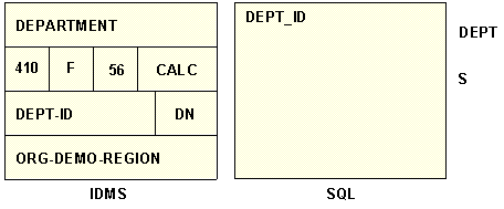
The following diagram illustrates how a record type is described
as a segment. The record type DEPARTMENT contains the field-type
DEPT-ID. Its corresponding server segment DEPT contains a field
named DEPT_ID.
Repeating fields on an IDMS/DB record type are defined as OCCURS
segments.
Network record types may be related to each other. These relationships
may be physical (using set connections) or logical (achieved through
an index or CALC field). The Adapter for IDMS/DB supports both physical
and logical relationships.
x
In an IDMS/DB database, physical relationships between
record types are achieved with pointers that correspond to IDMS/DB
sets. A set implements a one-to-many relationship between record
types. The server equivalent of a set is the parent/descendant relationship
between segments. In an IDMS/DB set, one record type acts as the
owner (the one side of the relationship) and one or more record
types act as the members (the many side of the relationship). A
single IDMS/DB record type can participate in several set relationships
as either the owner or the member.
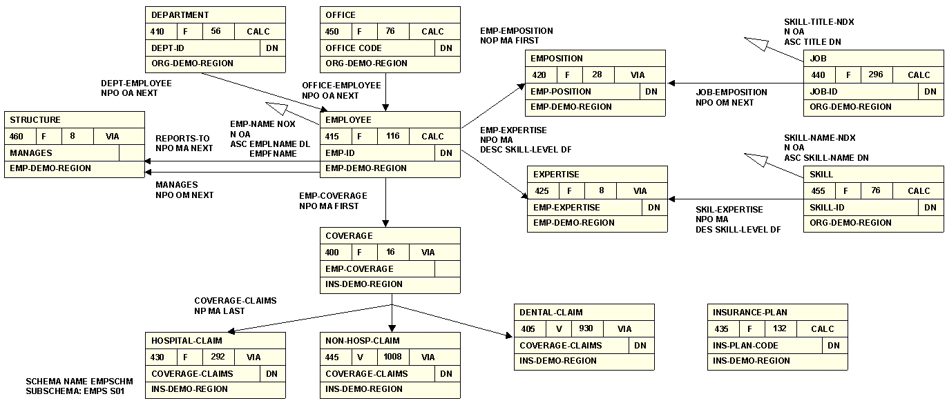
The IDMS/DB representation of record types and set relationships
within a database is called a Bachman diagram, also known as a data
structure diagram. In a Bachman diagram, a record type is depicted
as a box; a set, as a line with an arrow. Set names appear as labels
beside the arrows. The box that the arrow points to is the member
record type. Triangles indicate indexes. The next diagram is the
Bachman diagram for the IDMS/DB network subschema EMPSS01. Sections
of this diagram are referenced throughout these sections.
The following kinds of set-based relationships are depicted:
simple set, common owner, common member, multi-member, bill-of-materials
(simple and multi-tiered), and loop structures.
All relationships correspond to server structures and are explained
following the diagram:
x
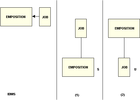
The following diagram illustrates the basic mapping
principle of a simple set: an IDMS/DB record type corresponds to
a segment; a set relationship corresponds to a parent/descendant
relationship.
This figure also illustrates a second principle: an IDMS/DB structure
can have more than one representation as a hierarchy. The type of
parent/descendant relationship required in the Master File depends
on whether the owner or the member record type is designated as
the parent segment.
The JOB-EMPOSITION set has two possible
representations:
- It shows the JOB record type, the owner in the set, mapped
to the server as the root segment. Since a member record type is
multiply-occurring (for example, several instances of EMPOSITION
records per JOB instance, indicating that many positions share one
job title and description), the EMPOSITION record type is displayed as
a non-unique descendant.
- It depicts the reverse. The EMPOSITION record type is the root
segment and JOB is the unique descendant, since an EMPOSITION instance
can have only one owner (only one job title and description per
position).
x
Given the rules in the previous example, consider a
more complex scenario called a common owner. A common owner structure
contains a record type that is the owner of two or more record types.
Several representations are possible.
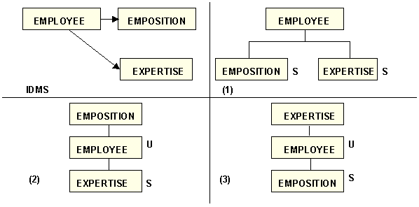
For example, the diagram below depicts
three ways to describe the EMPLOYEE, EXPERTISE, and EMPOSITION structure
in one Master File:
- It shows the EMPLOYEE record type, the owner in both sets,
mapped to the server as the root segment of EMPOSITION and EXPERTISE.
Since an EMPLOYEE record can have many EMPOSITION and EXPERTISE
records, both descendant records are non-unique.
- It depicts the EMPOSITION record type as the root segment of
EMPLOYEE, which acts as the parent of EXPERTISE. Since an EMPOSITION
record can have only one owner, EMPLOYEE is a unique descendant;
EXPERTISE is a non-unique descendant of EMPLOYEE.
- It depicts the EXPERTISE record type as the parent of EMPLOYEE,
which acts as the parent of EMPOSITION. EMPLOYEE is a unique descendant
and EMPOSITION is a non-unique descendant of EMPLOYEE.
x
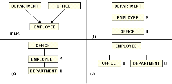
When an IDMS/DB record type is a member of two or more
sets, the association of the owner record type as the parent segment
must be abandoned for one or more sets, because a segment can have
only one parent. The diagram below displays the possible interpretations
for this IDMS/DB configuration.
In the diagram, the EMPLOYEE record type is a common member in
the DEPT-EMPLOYEE and the OFFICE-EMPLOYEE sets. This structure can
be described to the server in three ways:
- It shows DEPARTMENT as the root segment with EMPLOYEE as
its non-unique descendant. OFFICE is the unique descendant of EMPLOYEE.
- It depicts the reverse: OFFICE is the root segment; EMPLOYEE
is its non-unique descendant; and DEPARTMENT is the unique descendant
of EMPLOYEE.
- It shows the only other alternative: EMPLOYEE is the parent
of OFFICE and DEPARTMENT. Both are unique, since an EMPLOYEE can
belong to only one OFFICE and DEPARTMENT.
Notice that the rules for simple sets are still valid:
- If the owner record type is the parent segment, the member
record type as a descendant segment is non-unique.
- If the member record type is the parent segment, the owner record
type as a descendant segment is unique.
- A member or an owner record type may act as a root segment (the
server ignores whether the root segment is unique or non-unique).
It may be helpful to think of the hierarchical depiction of a
network structure as its navigational path. From an IDMS/DB standpoint,
panel 1 of the previous diagram shows that the IDMS/DB database
can be entered at the DEPARTMENT record type. The corresponding
EMPLOYEE record occurrences for a DEPARTMENT record occurrence can
be obtained by searching the DEPT-EMPLOYEE set. For each EMPLOYEE
record occurrence, obtaining the owner in the OFFICE-EMPLOYEE set
retrieves the corresponding OFFICE record occurrence. This is a
three-segment retrieval hierarchy that maps to server descriptions.
x
When there is more than one member record type, the
set is called a multi-member set. A multi-member set is represented
in the Master File exactly like a common owner set. The fact that
the two relationships are based on the same set is stated in the Access
File.
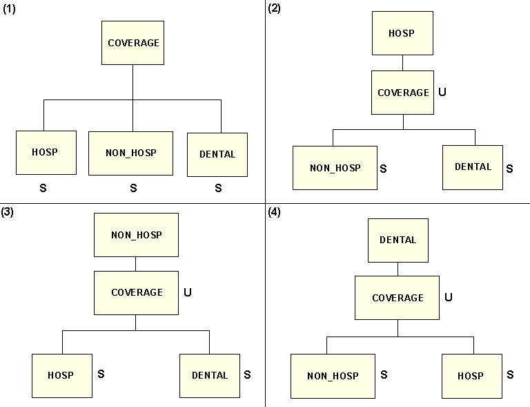
For example, to describe the COVERAGE
record type and its three members of the COVERAGE-CLAIMS set, you
may choose one of four ways as depicted in the following diagram:
- The first panel shows the COVERAGE record type, owner of
the multi-member set, as the root segment. Since several instances
of CLAIMS can be reported against one insurance policy (COVERAGE),
each member is a non-unique descendant.
- The second panel depicts HOSPITAL-CLAIM as the parent of COVERAGE,
and the other two member record types as descendants of COVERAGE.
In each case, a claim can be reported against only one insurance
policy. This explanation applies to panels 3 and 4 as well.
x
Bill-of-materials structures are classified as simple
or multi-tiered. In this section, the simple version is discussed
first.
An instance of two record types being linked by more than one
set is called a bill-of-materials structure. This structure describes
a many-to-many relationship between record occurrences of the same
record type. The member record type is the junction record type between
the two related owners.
For a simple bill-of-materials structure, the server requires
that the owner record type be represented as two or more segments
with different field names for the identical fields. This ensures
that, at retrieval time, the field names specified in the user's
request will provide the proper navigational path.
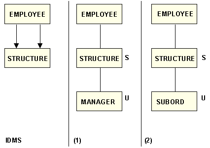
In the following diagram, the EMPLOYEE
and STRUCTURE record types are connected by two sets. This simple
bill-of-materials structure can be described two ways:
- As an employee-to-manager relationship. The EMPLOYEE record
type is the parent segment of the non-unique STRUCTURE segment using
the REPORTS-TO set. The STRUCTURE record type, in turn, is the parent
segment of the unique MANAGER segment using the MANAGES set (the
MANAGER segment duplicates the EMPLOYEE segment and its fields are
renamed).
- As an employee-to-subordinate relationship. The EMPLOYEE record
type is the parent segment of the non-unique STRUCTURE segment using
the MANAGES set. The STRUCTURE record type is the parent segment
of the unique SUBORD segment using the REPORTS-TO set (the SUBORD
segment duplicates the EMPLOYEE segment and its fields are renamed).
The previous diagram represents a two-tiered employee-to-employee
relationship. Multi-tiered relationships are extended bill-of-materials
structures. Multi-tiered relationships are created and used for
different levels of answer sets. The number of levels or tiers should be
kept to a minimum.
To determine the number of segments required
to describe an n-tiered relationship, use this formula:
Number of segments = (2 x number of tiers) - 1
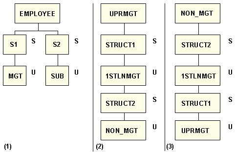
The following diagram is a three-tiered
version of the previous diagram:
- The first panel combines both views with EMPLOYEE as the
parent of two non-unique descendants, S1 and S2. Both S1 and S2,
in turn, are parents of a unique descendant, MGT and SUB, respectively
(S1 and S2 describe junction records that point to MGT and SUB).
- The second panel shows a three-tiered relationship between employees implemented
in a five-segment single-path hierarchy. The segments UPRMGT (upper management),
1STLNMGT (first-line management), and NON_MGT (non-management) all
describe the EMPLOYEE segment but have renamed fields (like S1 and
S2 above, STRUCT1 and STRUCT2 contain renamed fields that point
to descendant segments).
- The third panel depicts the opposite of panel 2.
x
Loop structures in IDMS/DB implement complicated relationships
among record types. For the server depiction of a loop, you must
select a record type to be the parent in the relationship.
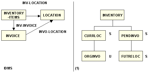
Suppose you had a loop structure like the one below. An INVOICE
record occurrence has an owner record occurrence (INVENTORY-ITEMS)
only if the invoice order is pending or has not been delivered.
The INVO-LOCATION set lists the location where an invoice item will be
or was delivered.
In panel 1 in the following diagram, the server translates this
structure as multi-tiered, with one tier of renamed segments. The
INVENTORY-ITEMS record type, in this case, acts as the root INVENTORY.
The LOCATION record type is mapped as the CURRLOC segment that lists
the location of items currently in stock. The INVOICE record type
is mapped as the PENDINVO segment that lists pending invoice orders.
Segments ORGINVO and FUTRELOC are required segments that rename
the data in record types INVOICE and LOCATION. The segment ORGINVO
contains historical information for an inventory item. The segment FUTRELOC
indicates where an ordered item will be delivered.
xCALC-Based and Index-Based Relationships
Logical relationships, unlike physical ones, are based
on the occurrence of the same data value in two different record
types. To make the parent/descendant connection, the Adapter for
IDMS/DB uses CALC fields or indices to locate the related record
occurrence(s). The related fields are not required to have the same
name in both record types, but the field format must be the same.
Note:
- WHEREs on CALC fields and indices are also
used to generate CALC and index calls to IDMS/DB.
- CALC or index fields can also be GROUPNAMEs, consisting of fields
contiguous in both parent and descendant segments. The format types
and lengths of the GROUP and its fields must be comparable in both
parent and descendant segments.
Like set-based descendants, CALC- and index-based descendants
are unique or non-unique, but this depends largely on how the DUPLICATES
parameter is specified in the Access File (the SEGTYPE parameter
for the descendant must also reflect the DUPLICATES parameter; for
example, CLCDUP=N, SEGTYPE=U). The server treats unique descendants
in the same manner regardless of what underlies the parent/descendant
relationship: set, index, or CALC field.
The COVERAGE and INSURANCE-PLAN record types in the diagram in Set-Based Relationships illustrate
a logical relationship. The field PLAN-CODE is common to both record
types. The parent/descendant relationship can be described to the
server if the:
- INSURANCE-PLAN record type has an index on PLAN-CODE.
- INSURANCE-PLAN record type is an IDMS/DB CALC record type with
PLAN-CODE as the CALC key.
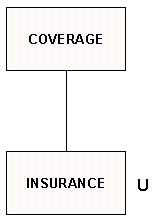
The diagram below depicts the server representation of the diagram
in Set-Based Relationships that
uses the CALC field method. The server interprets COVERAGE as the
parent segment and INSURANCE-PLAN as the descendant. Since the DUPLICATES
parameter is set to N (CLCDUP=N), the INSURANCE segment is unique.
xLogical Record Facility Concepts
The Adapter for IDMS/DB supports two kinds of LRF-based records:
- Logical Records (LR) are built from network record types.
They are not physically stored as such; instead, they are defined
within a subschema using DBA-supplied navigational paths. Logical
Records are created at execution time from real database records-types
based on DBA-supplied navigational paths and the SELECTs passed
to LRF from the server.
- Automatic System Facility (ASF) records are created by end-users
with the Automatic System Facility, a menu-driven front end to LRF.
This Facility generates subschemas and navigational paths based
on the user's menu selection.
The Adapter for IDMS/DB uses the IDMS/DB Logical Record Facility
(LRF) to retrieve and create ASF and LR records. In general, the
LRF-based records can contain information from several sources (both
DML created and ASF generated) that are located in several database
areas. All fields, records, and areas, however, must be defined
to the same subschema.
LRF-based records may be related to each other using an embedded
cross-reference. Your Master File can list up to 64 related LRF-based
records. Access Files can list an unlimited number of subschemas.
However, the server accesses up to 16 subschemas per request.
xLRF Records as Descendants
With the Adapter for IDMS/DB, you may create a parent/descendant relationship
between two LRF records if they share a common field or GROUP. Field
lengths and formats must be the same in both segments. The shared
fields are specified in the descendant segment declaration of the
Access File as the values of the KEYFLD/IXFLD pair.
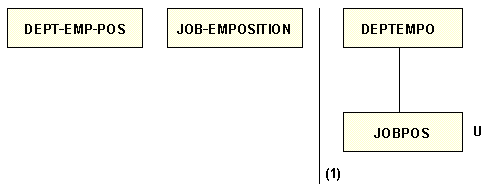
For example, in the diagram below, the LRF record DEPT-EMP-POS
is represented as the root segment DEPTEMPO; the LRF record JOB-EMPOSITION
as the unique segment JOBPOS. The related fields are POS_STRT_DR2
(the IXFLD value) and POS_STRT_DT1 (the KEYFLD value).
The restriction that the shared field in the descendant record
be a CALC or an indexed field does not apply to LRF records. However,
this kind of embedded cross-reference has one restriction: the IDMS/DB
path group for an LRF record that acts as the descendant segment
must contain a SELECT clause to process the implied WHERE clauses.
x
Syntax: How to Implement a Parent/Descendant Relationship With SELECT
SELECT
clauses are maintained by your DBA and should already be available
in your subschema. The following SELECT clauses can successfully
implement a parent/descendant relationship. They are listed in descending
order of efficiency
1. SELECT FOR FIELDNAME EQ fieldname
2. SELECT USING INDEX indexname
3. SELECT FOR FIELDNAME fieldname
4. SELECT FOR ELEMENT elementname
5. SELECT
where:
- fieldname
Is the joined-to IDMS/DB field name on the descendant record
type.
- indexname
Is the index set name to the joined-to field.
- elementname
Is the physical record type on which the joined-to field
is stored.
Note:
- If no specific
SELECT clause exists, a null SELECT clause (item 5) must be available
to process an answer set.
- LRF records that return partial record occurrences and user-defined
path status should not be used. If the adapter encounters a user-defined
path status, the status is interpreted as LR-ERROR and the retrieval
process is halted with messages EDA967 and EDA949.
- Do not confuse the use of the word SELECT with the SQL SELECT
statement. In the above example, the word SELECT is used to refer
to the IDMS/DB internal meaning.
xSummary of Network Relationships
As illustrated in the previous examples, there are four
ways to implement a network relationship. Each can be described
as a parent/descendant relationship:
- Owner/member
- Member/owner
- Field or GROUP/CALC field
- Field, GROUP/SPF, or Integrated Index
All four can be intermixed in one Master File. The actual underlying
connection (set, CALC, index) between parent and descendant is not
apparent to end users who specify field names. In addition, a Master
File can list record types from multiple subschemas, databases,
and dictionaries.
In server processing, the identity of the record type behind
a segment is invisible. The retrieval technique is followed in all
cases as if all segments were represented by distinct records. Within
IDMS/DB, currencies are maintained by storing the DBKEYs of record
types and retrieving the record occurrence again, when needed.
The top-to-bottom order in which segments are defined (the chains
of parent/descendant relationships) corresponds to structural relationships
among the IDMS/DB record types. This top-to-bottom order is logically
significant; the left-to-right order, on the other hand, is not.


